-
Connect to your computer
Plug a USB-C cable from the RAK4631 (or WisBlock base board) into your computer. Use a data-capable cable — charge-only cables will not work.
Use Google Chrome only. Safari and Firefox are not supported.
-
One-time only
Install the OTAFIX bootloader
Do this step once. OTAFIX enables future repeater updates over Bluetooth.
-
Enter UF2 bootloader mode
With the RAK4631 connected, quickly double-press reset. A USB drive named RAK4631 (~32 MB) should appear.
-
Download the OTAFIX bootloader
-
Install the bootloader
Drag the UF2 file onto the RAK4631 USB drive. Do not unplug during update.
-
Verify OTAFIX is installed
Re-enter UF2 mode. Open
INFO_UF2.TXT— version must include OTAFIX.
-
-
Open the MeshCore flasher
In Chrome, go to meshcore.io/flasher.
-
Select board, role, and mode
Select RAK WisBlock/WisMesh (RAK4631), choose Repeater, then select DFU mode (not UF2 mode).
-
Connect and flash
Click Connect, pick the serial port, and flash. Do not disconnect until the flasher reports success.
If not detected, double-tap reset and try Connect again.
-
Configure your repeater
After flashing, select Configure via USB, then Connect.
-
Set name
Name & Location → Name
-
Set coordinates (optional)
Latitude and Longitude
-
Set admin password
Access → New Admin password
-
Change preset to USA
Radio settings → Preset → USA/Canada (Recommended)
-
Save settings
Scroll to bottom. Click Save settings.
Important: Changes are not applied until you save.
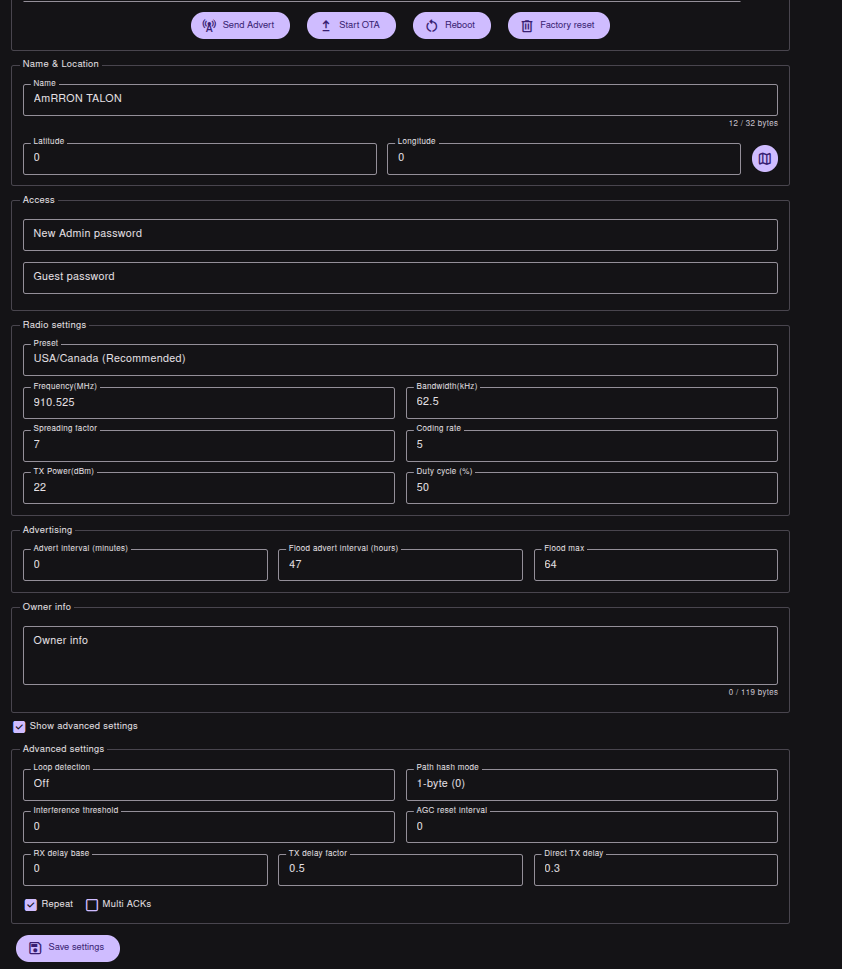
Field reference:
- Name & Location — Name, Latitude, Longitude
- Access — New Admin password
- Radio settings — Preset → USA/Canada (Recommended)
- Save settings — bottom of page (required)
-
-
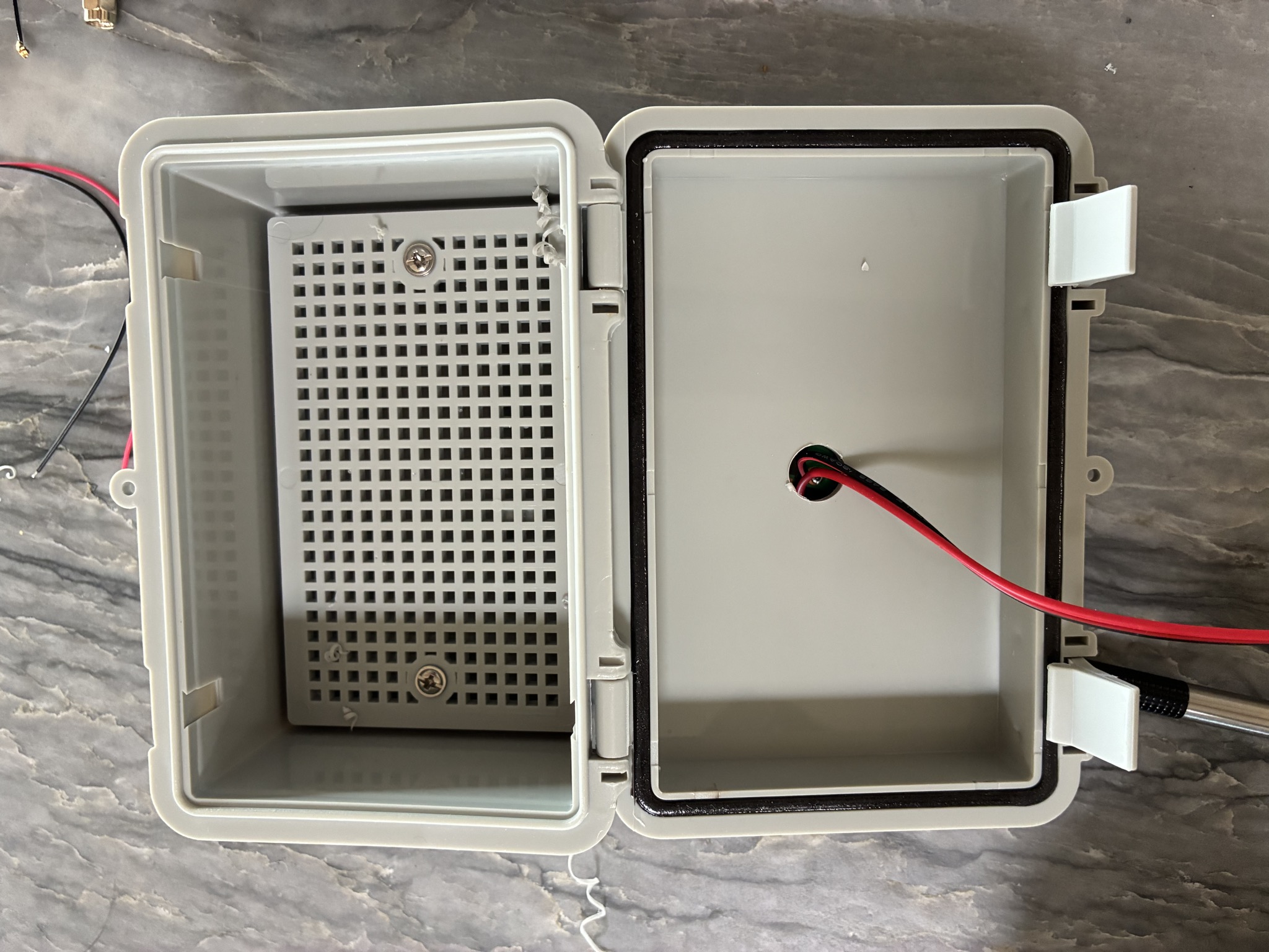
Solar panel cable entry
With the RAK4631 flashed and configured, move to final assembly. Drill a 1/2 inch hole in the center of the enclosure lid for the solar panel leads.
-
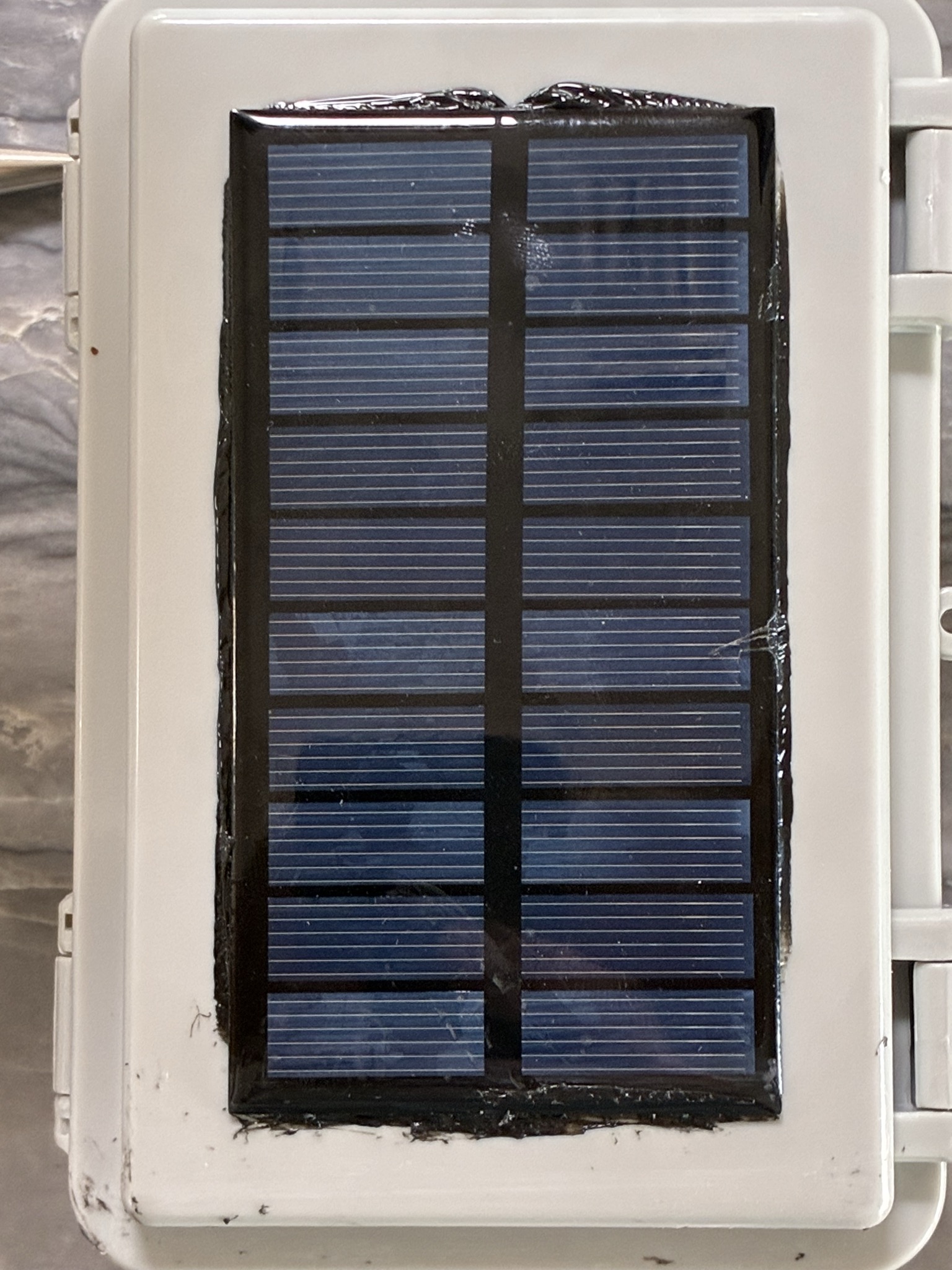
Solar panel installation
Apply adhesive or silicone sealant around the solar panel and route the leads through the lid hole from Step 07.
-
Do not skip
Critical JST 2.0 polarity correction
IMPORTANT: The JST 2.0 battery lead as received has reversed polarity — there is no industry standard for which lead is positive. Remove the pins and swap the leads before connecting power.
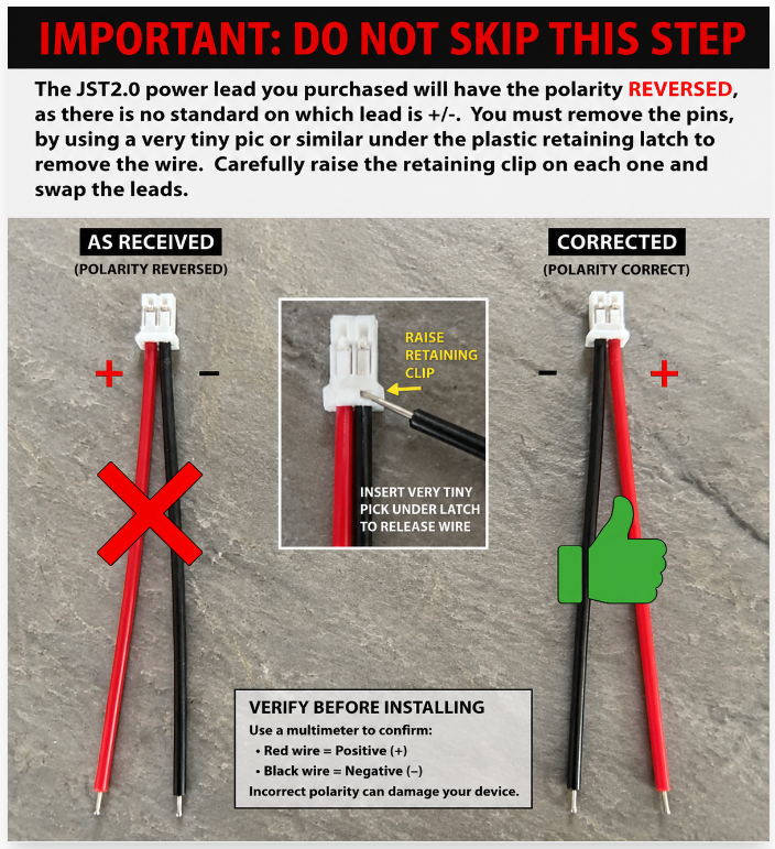
Use a very tiny pick under the plastic retaining latch to release the wire, raise the retaining clip, and swap the leads. Verify with a multimeter before installing: red = positive (+), black = negative (−). Incorrect polarity can damage your device.
-
Power connection reference
Use the approved connector orientation: JST 1.5 (solar) on the left, JST 2.0 (battery) on the right.
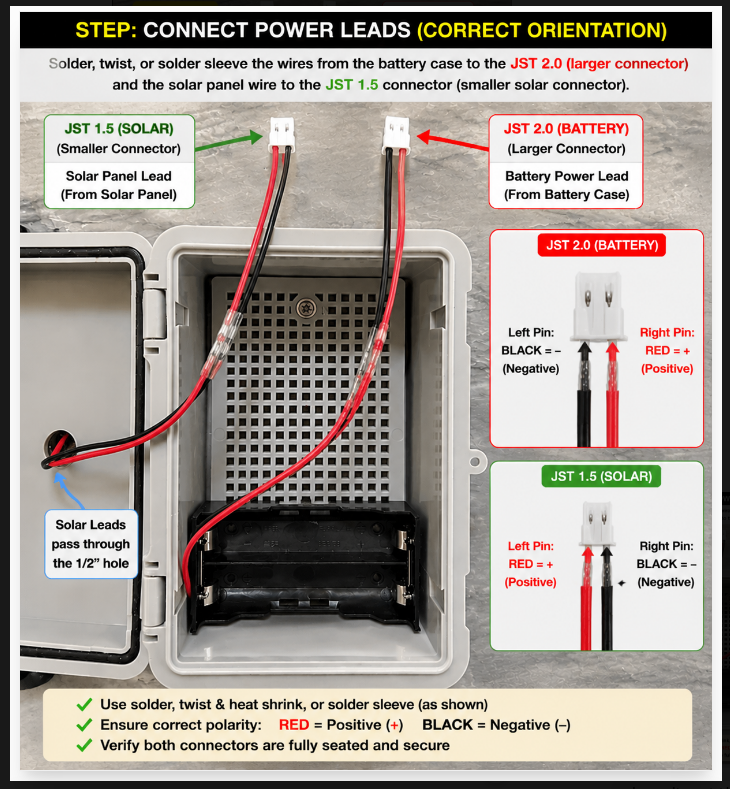
Solder, twist and heat-shrink, or use a solder sleeve. Confirm polarity with a multimeter and verify both connectors are fully seated before closing the case.
-
Charge batteries
Fully charge both 18650 cells before installation. Use a dedicated Li-ion charger (e.g. the IMREN 4-bay USB-C charger) and confirm each cell reads ~4.2V before seating it in the holder — do not install partially charged or unverified cells.
-
RAK4631 / battery installation
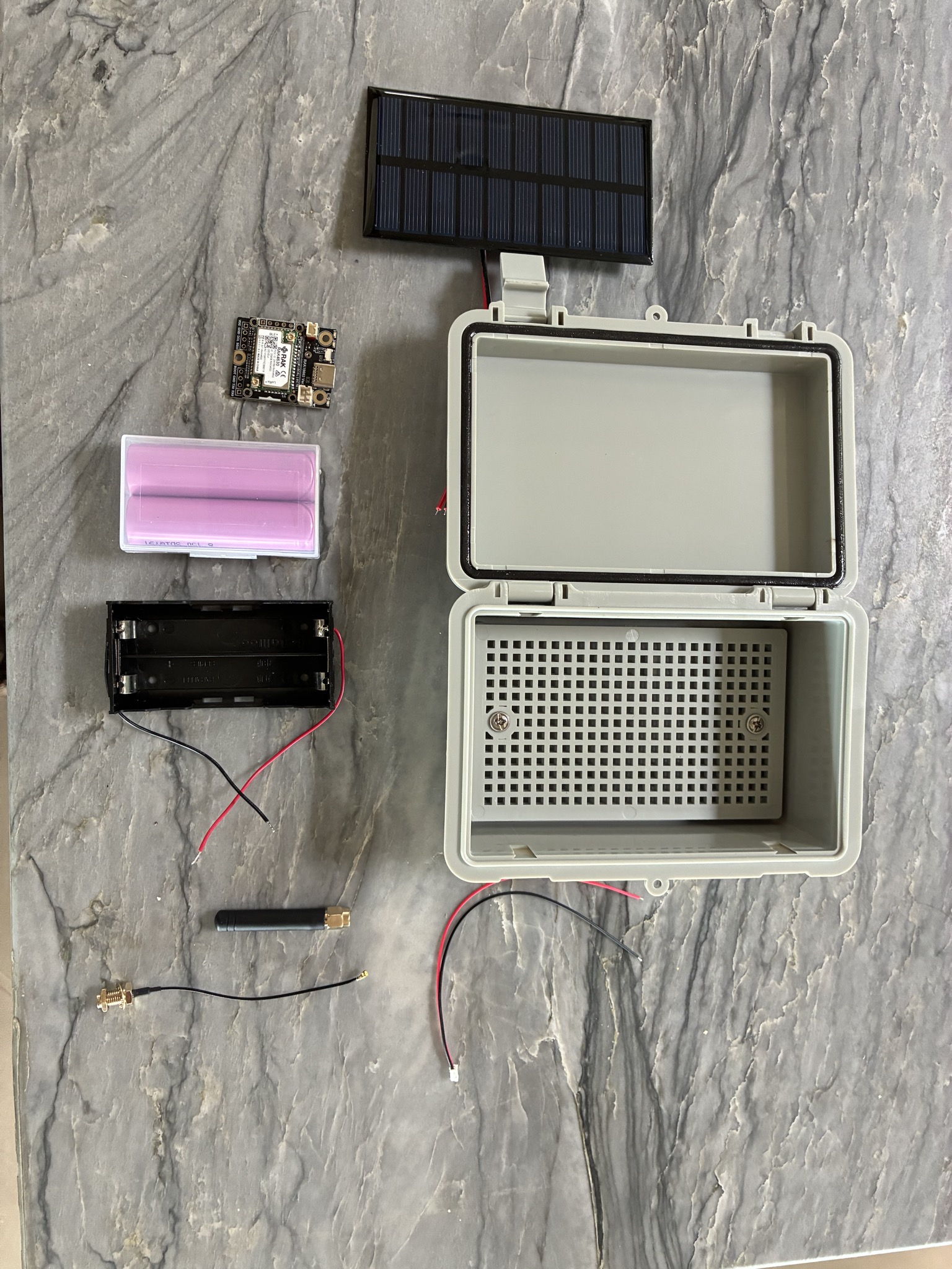
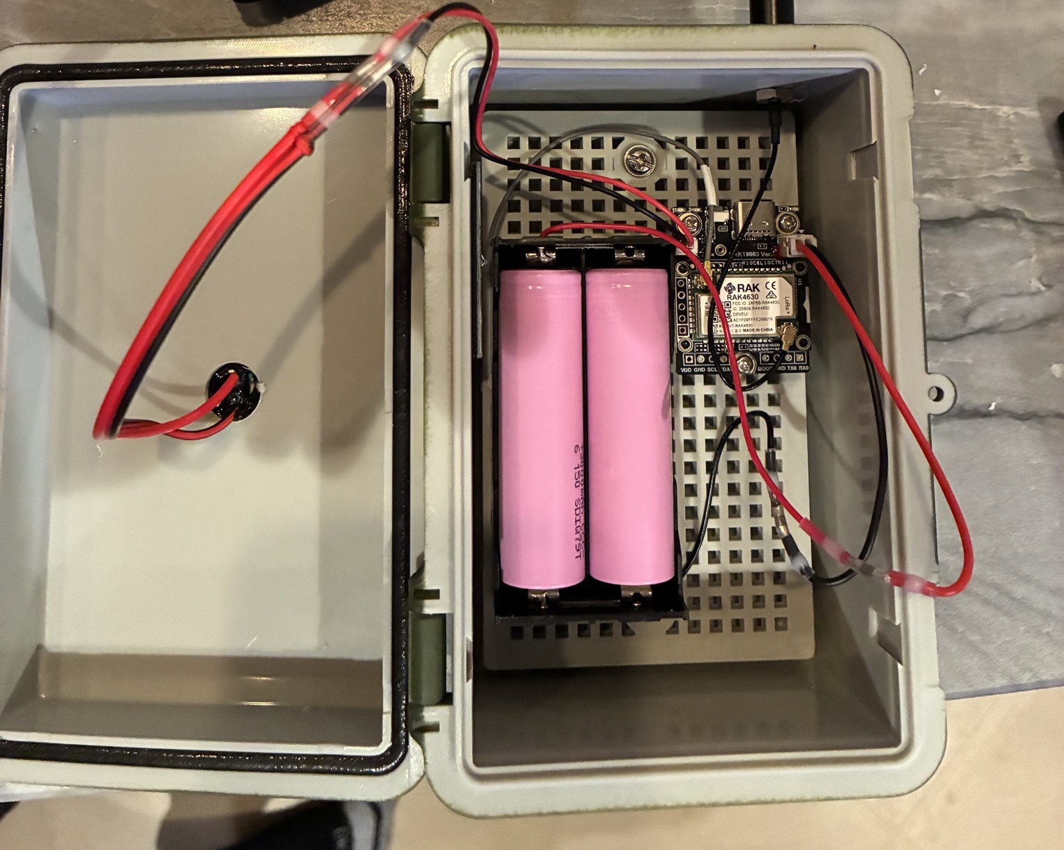
Install the battery holder, M2.5 standoffs, and antenna bulkhead. Seat the RAK4631 board and connect the battery and solar leads.
-
Antenna installation
Seat the IPX connectors carefully. Avoid cable twist or preload on the pigtail.
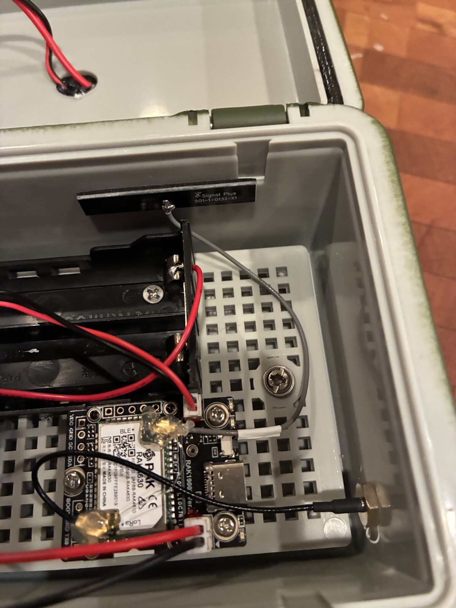
Apply hot glue as desired to the IPX connectors to ensure no movement or disconnect.
Field deployment checklist
- Firmware flashed
- JST polarity verified
- Solar installed
- Antenna connected
- Batteries installed correctly
- Enclosure sealed
- Radio tested
- Hoist deployment complete